
Our TGV horns
Pneumatic horn: operation and manufacturing
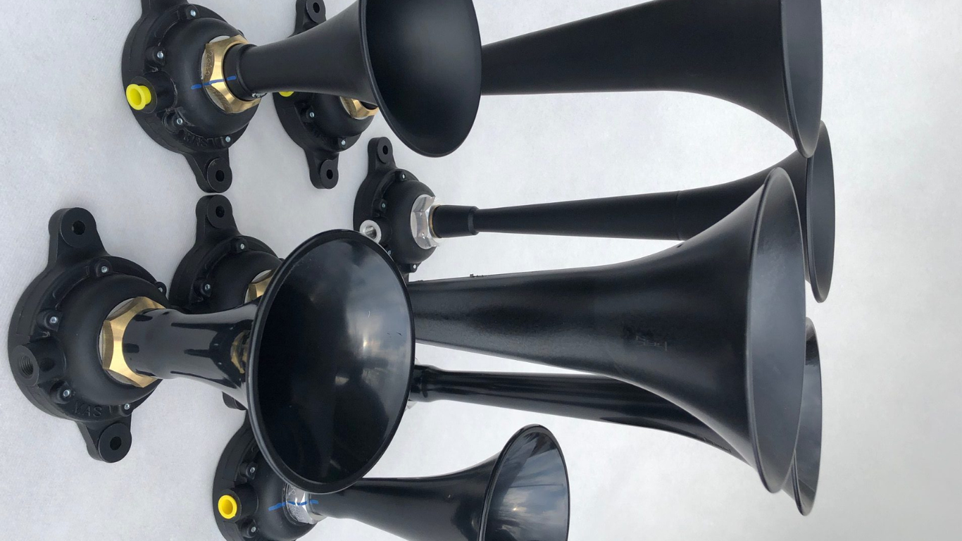
Composition of the horn
The clamping nut ensures mechanical assembly
The clamping nut plays a crucial role in the assembly of the horn. It ensures a precise and secure mechanical connection between the acoustic body and the bell.
The nut is tightened to a controlled torque using a torque wrench in order to:
- to ensure optimal pressure on the membrane,
- to ensure the repeatability of acoustic performance,
- to avoid any drift in settings over time.
Once tightened, the nut is marked to indicate the assembly and allow for immediate identification in case of subsequent disassembly. This assembly method directly contributes to the acoustic quality, safety of use, and durability of the horn.
An acoustic body incorporating a vibrating membrane
The acoustic body is the central element of the pneumatic horn. It receives compressed air and transforms pneumatic energy into acoustic vibration.
Inside the acoustic body is a vibrating membrane, specially designed to oscillate under the effect of air pressure. This membrane generates the primary sound wave, which is then amplified and directed by the horn.
The acoustic body is sized to:
- ensure high mechanical stability,
- to ensure a consistent acoustic response,
- to withstand the stresses associated with intensive use in an industrial environment.
Its manufacturing process allows for reliable and consistent operation, even in environments subject to variations in pressure, temperature, or humidity.
Brasage
- of thunder and brass branch (bells in 2 pieces)
- of the mouthpiece on the brass pavilion
Painting
Torque tightening/screwing
We have a semi-anechoic chamber for calibrating audible alarms. We use a sound level meter and acoustic software to measure the power in dB and the fundamental frequency of the alarms. Our Class 1 sound level meters are calibrated annually by a certified laboratory.
The process below is applied to each warning device, thus ensuring complete traceability:
1
Manual adjustment of the horn on a test bench under the required air pressure
2
Tighten the nut with a torque wrench
3
A blue marking has been added to indicate the tightening point, to signal any potential future disassembly.
4
Audible alarm numbering and computer saving of measured performance